The hidden engineering behind better traffic signs

Figure 1. Viaduct-mounted static traffic sign. Image: Arup

Sydney Airport’s new signage system uses automatic dimming and precision optics to solve a problem most drivers never notice.

Claude Zhu is an electrical engineer at Arup in Perth and has published more than 20 articles in industry journals and magazines.

As part of a broader initiative to improve ground transport efficiency, enhance passenger experience and future-proof its infrastructure, Sydney Airport commissioned a significant upgrade of its static traffic signs to variable message sign (VMS) network.

The project involved the installation of high-resolution, full-colour LED matrices to facilitate the following functions:


Claude Zhu
  • Real-time communication: Deliver real-time information to drivers, such as traffic conditions, speed limits, detours, safety warnings and travel times, and handle dynamic lane allocation
  • Operational agility: Remote management of content without the need for manual sign replacement
  • Enhanced visibility: Superior legibility in all weather conditions, throughout different times of a day

VMS features

Figure 1 (at the top of the article) shows a viaduct mounted static traffic sign to be upgraded at Sydney Airport. A white strip was pasted on the sign, likely with the intention to cover or modify the incorrect information.

Figure 2 shows a gantry mounted VMS installed at an earlier stage. It operates 24/7 and requires minimal labour to change the display content.
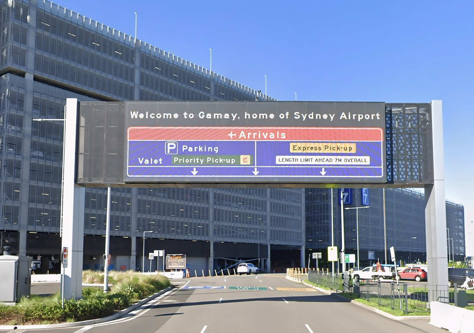
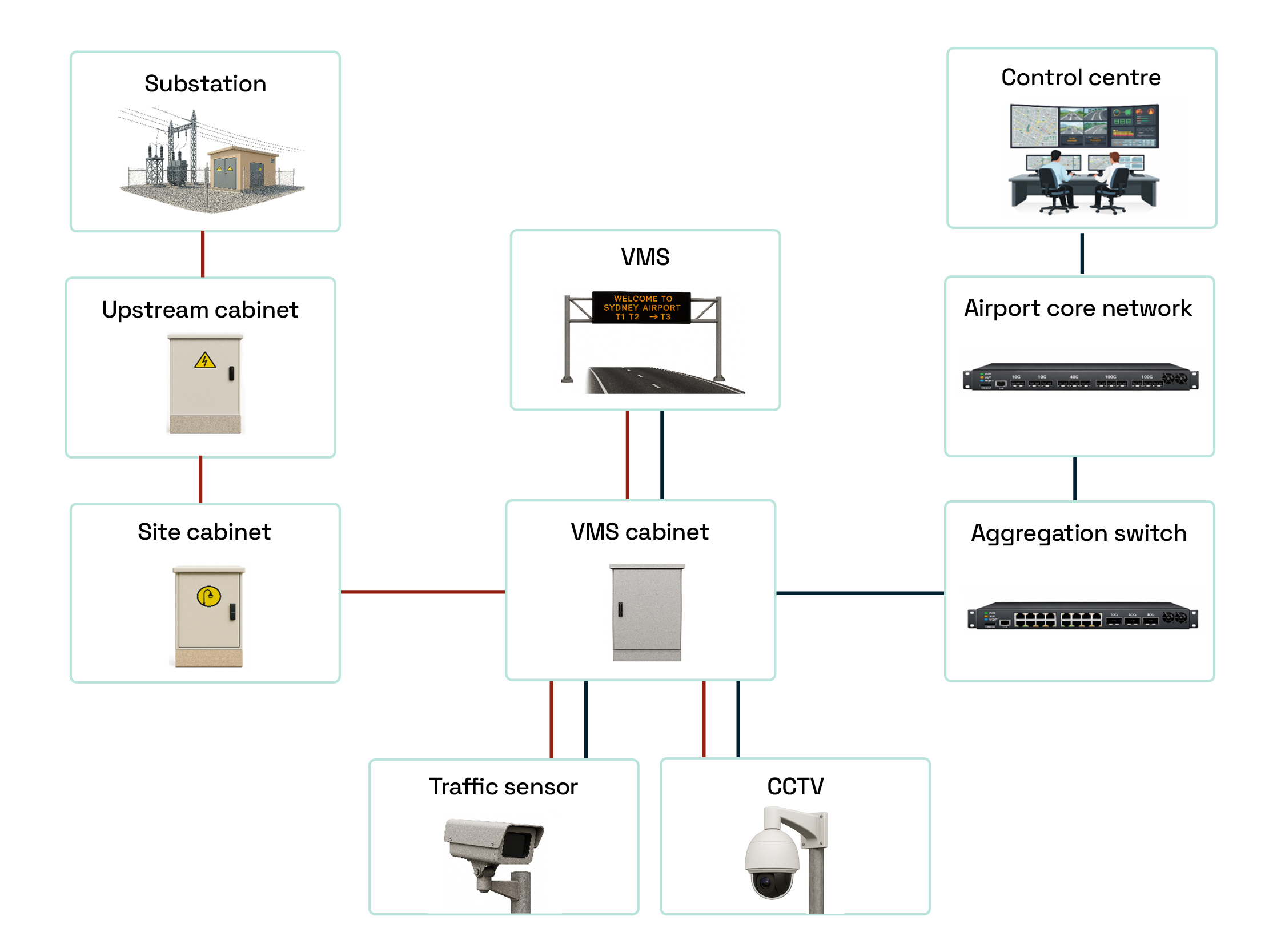
Figure 2. A gantry-mounted VMS. Image: Google Street View

The LED-featured VMS has the following features: 

  • Dimensions: The proposed signs have a display area of 20-60 m².
  • Pixel pitch and resolution: The display utilises a 16 mm pixel pitch, a considerably higher density than the standard highway VMS (20-30 mm), creating “retina-grade” clarity for viewers.
  • Power and thermal: The signs usually have a power consumption of 1.8-2.8 kW, similar to a domestic hair dryer. The LEDs are driven at less than 10 per cent of their rated capacity, significantly reducing heat generation and extending the operational lifespan of the diodes.

Upgrade methodology

This project aimed to integrate the power and communications through existing airport-owned conduit infrastructure, supplying to the VMS sites.

Figure 3 demonstrates an architecture diagram of the proposed VMS system, including power (red lines) and communication (navy blue lines) networks. 

The core structure of the system consists of a VMS cabinet, display, traffic sensor and CCTV. In the case of an incident, the sensor and CCTV send site data to the alarm at the control centre to provide warnings, then the operators decide relevant messages to present on the VMS.

Figure 3. Architecture diagram of a VMS

The Australian and New Zealand electrical installation standard AS/NZS 3000 generally stipulates the maximum voltage drop of 5 per cent at the VMS display.

Technical scope of the upgrade included:

  • Provision of 240V AC power to new VMS units, including surge protection and sub-circuit upgrades
  • Installation of fibre-optic cables to integrate each VMS into the airport’s traffic control centre via IP, without complex intermediate roadside relays
  • Utilisation of the existing airport conduit network to minimise surface disruption and civil costs

Display visibility

The legibility of a VMS at various viewing distances depends on luminance contrast ratio – that is, the brightness difference between the display contents and the background on the signage. 

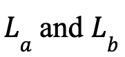
Luminance contrast ratio can be calculated by where:
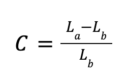
  •  is the luminance from the sign with all pixels active, under external illumination
  • is the luminance from the sign with all pixels inactive, under external illumination
  • Both  are in cd/m²

Figure 4 shows how the luminance contrasts impact VMS visibility, in the daytime scenario. Luminance levels shall be sufficient to ensure visibility, a contrast ratio of between 8-12 can generally provide optimum message clarity.¹
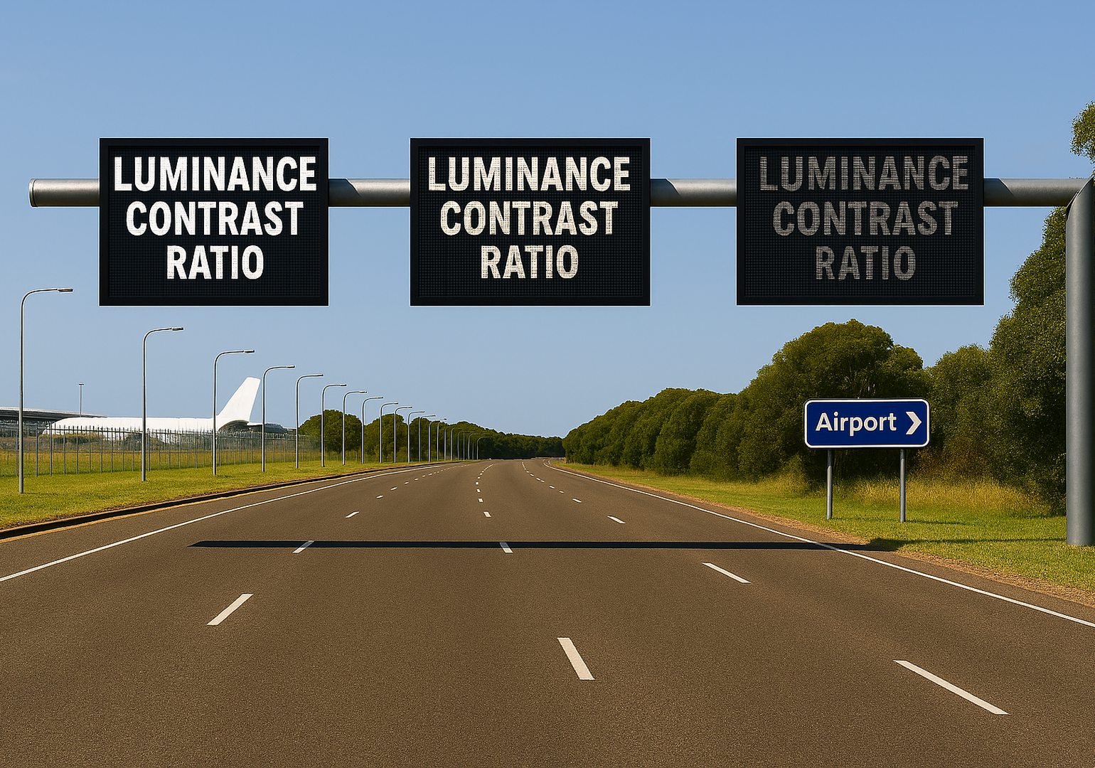
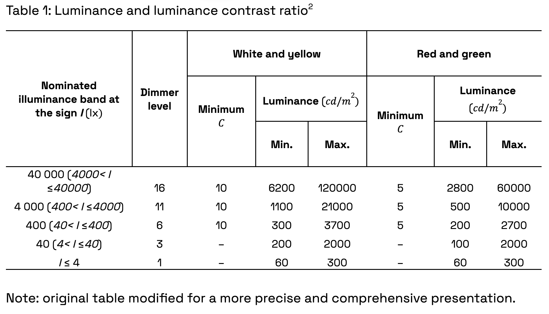
Figure 4. VMS visibility with different luminance contrast

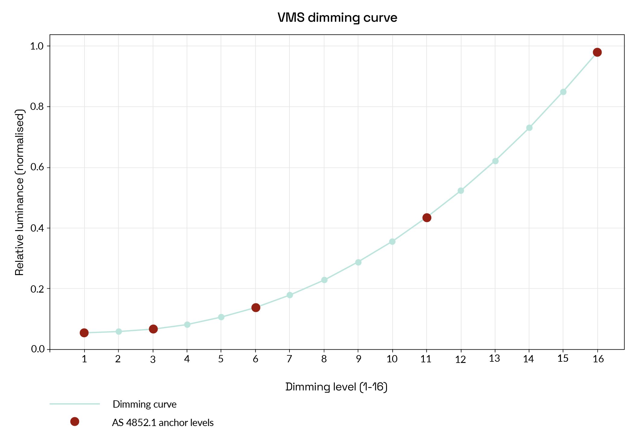
The Australian standard AS 4852.1 (Variable Message Signs, Part 1: Fixed Signs) specifies minimum luminance and contrast thresholds for compliances.

Figure 5. A typical VMS dimming curve

Table 1 summarises the required luminance and contrast ratio at five designated dimmer levels, corresponding to different daylight conditions. Figure 5 represents a practical dimming pattern reflecting Table 1, with normalised luminance outputs.

The standard AS 4852.1 does not force manufacturers to specify the exact values, as long as they meet the minimum and maximum value requirements. 

A few observations from Table 1 and Figure 5:

  • Higher environmental illumination e.g. sunlight, calls for greater VMS luminance and faster dimming.
  • At night when there is no sunlight (I ≤ 40 lx), a minimum luminance contrast ratio (C) is not required and the dimming is slower.
  • In the daytime (I > 40 lx), red and green colours provide better visibility than white and yellow ones.

Glare and obtrusive light control

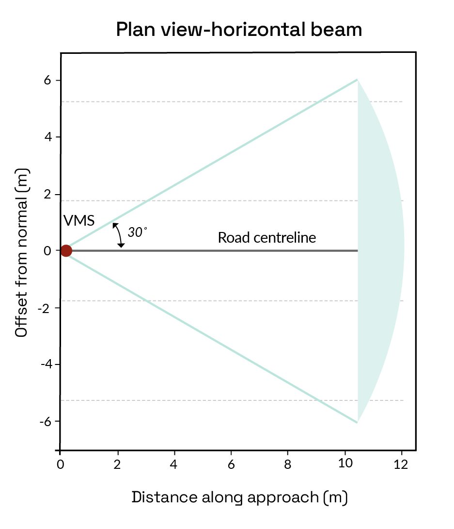
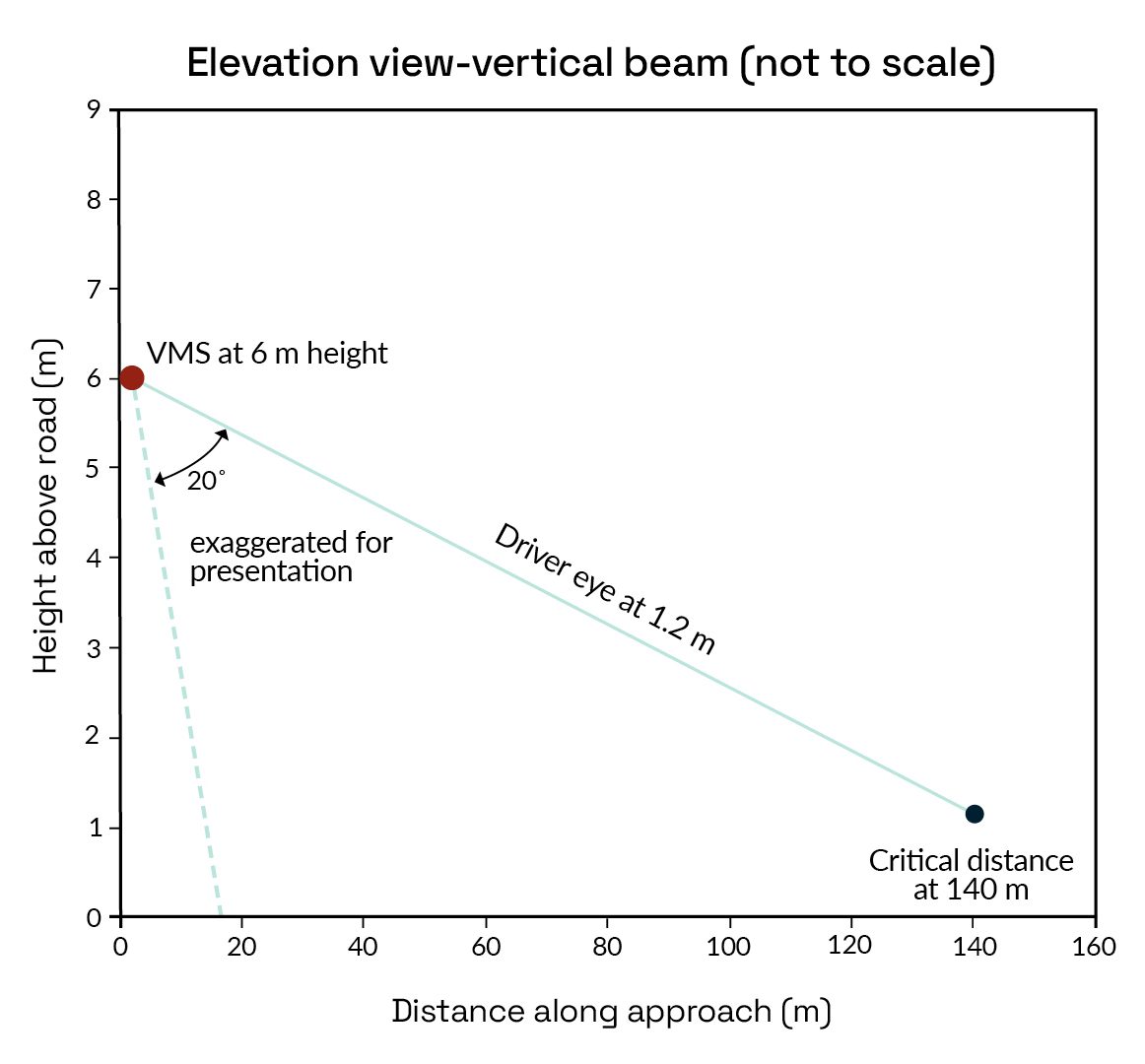
Precise optical design concentrates luminous intensity into the driver viewing cone (approximately ±30° horizontal and predominantly downward -10° to -20° vertical), rather than emitting broadly into the sky or far off‑axis directions.

Figure 6. VMS beam distribution

Figure 6 explains typical VMS beam distribution. The sign is aimed so the optical normal intercepts the driver’s eye height (1.2 m) at the critical reading distance (e.g. 140 m), ensuring that the on‑axis luminance and luminance ratio requirements are met under bright sun while minimising night‑time glare and sky-glow through automatic dimming. 

Conclusions

Overcoming difficulties and challenges, the VMS upgrade at Sydney Airport has endeavoured to provide the optimum signage visibility, travel safety and operational efficiency, which would define it as a world-class ITS project to be learnt from.

READ: Why carpark speed humps hurt so much – and how physics could fix them

References

¹Austroads. “Guide to Traffic Management, Part 10: Traffic Control and Communication Devices.” 2019. Available: https://austroads.gov.au/publications/traffic-management/agtm10

²Standards Australia. “AS 4852.1 – Variable Message Signs, Part 1: Fixed Signs.” 2019.

Exit mobile version